

Technical Specs
| Parameter | Unit | Value | |
|---|---|---|---|
| Voltage Rating | Volts | 600 VAC | |
| Amp Rating | Amps | 400-5000 Amps | |
| Circuits | No | 3F/3H, 3F/3H+T, 3F/4H, 3F/4H+T | |
| Neutral | % | 0%, 50% o 100% | |
| Ground | % | 0%, 25% | |
| Conductor Material | -- | Electrolitic Copper (>99.9% IACS) | |
| 6101-T6 Aluminum (>61% IACS) | |||
| Insulation | -- | Powder epoxy paint applied via electrostatic gun | |
| Dielectric strenght: 45kV/mm | |||
| Heat resistance: 130°C (Class B) | |||
| Joints | -- | Single-bolt pressure joint for easy install/uninstall | |
| Silver-plated (standard) joint surface for maximum conductivity | |||
Especificaciones Técnicas
| Parámetro | Unidad | Valor |
|---|---|---|
| Tensión | Voltios | 600 VAC |
| Ampacidad | Amperios | 400-5000 Amps |
| Circuitos | No | 3F/3H, 3F/3H+T, 3F/4H, 3F/4H+T |
| Sección de Neutro | % | 0%, 50% o 100% |
| Sección de Tierra | % | 0%, 25% |
| Material Conductor | -- | Cobre Electrolítico >99.9% IACS |
| Aluminio 6101-T6 >61% IACS | ||
| Aislamiento | -- | Recubrimiento de pintura epóxica en polvo mediante aplicación electrostática |
| Rigidez Dieléctrica de 46kV/mm | ||
| Resistencia al calor: 130°C (Clase B) | ||
| Empalmes | -- | Empalme a presión tipo “joint” con perno único para fácil montaje y desmontaje |
| Área de unión cubiertas en plata (estándar) para maximizar la conductividad |
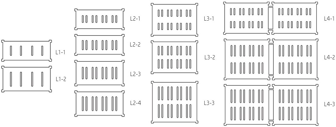
Measurements and Weight
| Amps (A) | Conductor | W x H(inch) | Weight (Lb/ft) | Fig. |
|---|---|---|---|---|
| 3P/4H+50%T | ||||
| 400 | ALUMINUM | 10 x 4.5 | 9 | L1-1 |
| 630 | 10 x 5.5 | 10 | L1-2 | |
| 800 | 10 x 4.5 | 9 | L2-1 | |
| 1000 | 10 x 4.5 | 10 | L2-2 | |
| 1200 | 10 x 5.5 | 11 | L2-3 | |
| 1350 | 10 x 5.5 | 12 | L2-4 | |
| 1600 | 10 x 7.5 | 15 | L3-1 | |
| 2000 | 10 x 7.5 | 17 | L3-2 | |
| 2500 | 10 x 9.5 | 21 | L3-3 | |
| 3000 | 20-5/8 x 7.5 | 31 | L4-1 | |
| 4000 | 20-5/8 x 9.5 | 43 | L4-2 | |
| 5000 | 20-5/8 x 9.5 | 50 | L4-3 |
Dimensiones y Pesos
| Amperios (A) | Conductor | W x H(pulg) | Peso (Lb/pie) | Fig. |
|---|---|---|---|---|
| 3P/4H+50%T | ||||
| 400 | ALUMINIO | 10 x 4.5 | 9 | L1-1 |
| 630 | 10 x 5.5 | 10 | L1-2 | |
| 800 | 10 x 4.5 | 9 | L2-1 | |
| 1000 | 10 x 4.5 | 10 | L2-2 | |
| 1200 | 10 x 5.5 | 11 | L2-3 | |
| 1350 | 10 x 5.5 | 12 | L2-4 | |
| 1600 | 10 x 7.5 | 15 | L3-1 | |
| 2000 | 10 x 7.5 | 17 | L3-2 | |
| 2500 | 10 x 9.5 | 21 | L3-3 | |
| 3000 | 20-5/8 x 7.5 | 31 | L4-1 | |
| 4000 | 20-5/8 x 9.5 | 43 | L4-2 | |
| 5000 | 20-5/8 x 9.5 | 50 | L4-3 |
Voltage Drop
| Rated Current (A) | Line-Line Voltage Drop (mV/m) at rated current per power factor | |||||||||
|---|---|---|---|---|---|---|---|---|---|---|
| 1.00 | 0.90 | 0.80 | 0.70 | 0.60 | 0.50 | 0.40 | 0.30 | 0.20 | 0.10 | |
| 400 | 38.79 | 55.76 | 60.30 | 61.52 | 61.82 | 61.52 | 61.21 | 60.30 | 58.18 | 51.52 |
| 600 | 38.18 | 63.64 | 72.73 | 75.15 | 76.67 | 76.67 | 76.36 | 75.45 | 73.64 | 68.18 |
| 800 | 56.06 | 62.12 | 60.61 | 58.18 | 54.55 | 50.91 | 46.36 | 41.82 | 36.67 | 26.67 |
| 1000 | 56.06 | 61.21 | 60.00 | 57.27 | 53.64 | 50.00 | 45.45 | 40.91 | 36.06 | 26.36 |
| 1200 | 50.91 | 56.67 | 57.88 | 56.06 | 53.33 | 50.00 | 46.36 | 42.42 | 37.88 | 28.48 |
| 1350 | 50.00 | 55.45 | 55.15 | 53.33 | 50.61 | 47.58 | 43.64 | 40.00 | 35.76 | 26.97 |
| 1600 | 52.12 | 57.88 | 56.67 | 54.55 | 51.82 | 47.88 | 44.24 | 39.39 | 35.15 | 25.45 |
| 2000 | 52.12 | 58.18 | 56.97 | 54.24 | 51.21 | 47.88 | 44.24 | 39.70 | 35.45 | 26.06 |
| 2500 | 48.48 | 53.94 | 53.03 | 51.82 | 48.79 | 46.36 | 42.73 | 38.79 | 34.24 | 25.15 |
| 3000 | 49.09 | 54.55 | 53.64 | 59.39 | 48.79 | 44.85 | 40.91 | 37.27 | 32.73 | 23.64 |
| 4000 | 46.06 | 53.33 | 51.52 | 48.48 | 46.67 | 42.42 | 38.18 | 35.76 | 30.91 | 23.03 |
| 5000 | 46.97 | 53.03 | 53.03 | 52.42 | 50.61 | 46.97 | 43.94 | 39.39 | 34.85 | 24.24 |
Caídas de Tensión
| Corriente Nominal (A) | Caída de Tensión Linea-Linea (mV/m) a corriente nominal según factor de potencia | |||||||||
|---|---|---|---|---|---|---|---|---|---|---|
| 1.00 | 0.90 | 0.80 | 0.70 | 0.60 | 0.50 | 0.40 | 0.30 | 0.20 | 0.10 | |
| 400 | 38.79 | 55.76 | 60.30 | 61.52 | 61.82 | 61.52 | 61.21 | 60.30 | 58.18 | 51.52 |
| 600 | 38.18 | 63.64 | 72.73 | 75.15 | 76.67 | 76.67 | 76.36 | 75.45 | 73.64 | 68.18 |
| 800 | 56.06 | 62.12 | 60.61 | 58.18 | 54.55 | 50.91 | 46.36 | 41.82 | 36.67 | 26.67 |
| 1000 | 56.06 | 61.21 | 60.00 | 57.27 | 53.64 | 50.00 | 45.45 | 40.91 | 36.06 | 26.36 |
| 1200 | 50.91 | 56.67 | 57.88 | 56.06 | 53.33 | 50.00 | 46.36 | 42.42 | 37.88 | 28.48 |
| 1350 | 50.00 | 55.45 | 55.15 | 53.33 | 50.61 | 47.58 | 43.64 | 40.00 | 35.76 | 26.97 |
| 1600 | 52.12 | 57.88 | 56.67 | 54.55 | 51.82 | 47.88 | 44.24 | 39.39 | 35.15 | 25.45 |
| 2000 | 52.12 | 58.18 | 56.97 | 54.24 | 51.21 | 47.88 | 44.24 | 39.70 | 35.45 | 26.06 |
| 2500 | 48.48 | 53.94 | 53.03 | 51.82 | 48.79 | 46.36 | 42.73 | 38.79 | 34.24 | 25.15 |
| 3000 | 49.09 | 54.55 | 53.64 | 59.39 | 48.79 | 44.85 | 40.91 | 37.27 | 32.73 | 23.64 |
| 4000 | 46.06 | 53.33 | 51.52 | 48.48 | 46.67 | 42.42 | 38.18 | 35.76 | 30.91 | 23.03 |
| 5000 | 46.97 | 53.03 | 53.03 | 52.42 | 50.61 | 46.97 | 43.94 | 39.39 | 34.85 | 24.24 |
Short-Circuit Capacity
| Rated Current (A) | Short-Circuit Level (kA) | |
|---|---|---|
| Asymmetrical | Symmetrical | |
| 400 | 25 | 23 |
| 600 | 27 | 23 |
| 800 | 47 | 41 |
| 1000 | 55 | 48 |
| 1200 | 65 | 57 |
| 1350 | 75 | 65 |
| 1600 | 92 | 82 |
| 2000 | 110 | 96 |
| 2500 | 150 | 130 |
| 3000 | 184 | 164 |
| 4000 | 250 | 227 |
| 5000 | 250 | 250 |
Capacidad de Cortocircuito
| Corriente Nominal (A) | Nivel de Corto-Circuito (kA) | |
|---|---|---|
| Asimétrico | Simétrico | |
| 400 | 25 | 23 |
| 600 | 27 | 23 |
| 800 | 47 | 41 |
| 1000 | 55 | 48 |
| 1200 | 65 | 57 |
| 1350 | 75 | 65 |
| 1600 | 92 | 82 |
| 2000 | 110 | 96 |
| 2500 | 150 | 130 |
| 3000 | 184 | 164 |
| 4000 | 250 | 227 |
| 5000 | 250 | 250 |
Quality Certificates
Certificado de Calidad
